Definition of Fused Quartz
Fused Quartz / Fused Silica is an amorphous glass obtained by melting and rapidly cooling high-purity silicon dioxide. It features an extremely low coefficient of thermal expansion, excellent optical transmission (covering UV–visible–infrared ranges), high thermal resistance, and strong chemical corrosion resistance. These properties make it a key material in demanding applications such as semiconductor equipment components, aerospace sensors, and vacuum chambers.
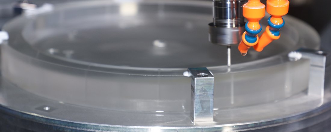
Fused Quartz Parts Machining Capabilities
Machining Equipment: Multi-axis CNC precision milling, laser cutting & marking, ultra-precision surface grinding & polishing, ultrasonic cleaning, and cleanroom packaging.
High-Precision Capabilities:
Complex shapes: tolerances up to ±0.01 mm
Cylindrical/shaft components: tolerances up to ±0.001 mm
Surface flatness: up to 0.001 mm
Optical flatness: up to 1/20λ (depending on wavelength)
Micro-holes: diameters as small as 0.1 mm (tolerance ±0.01 mm)
Surface roughness: Ra 0.01 μm for structural parts, Ra 0.002 μm for optical components
Surface Treatment: Polishing, optical coating
Inspection Equipment: Coordinate Measuring Machine (CMM), interferometer, profilometer, surface roughness tester, roundness tester, etc.
Quality System: ISO 9001 & ISO 14001, ISO 13485 certified. Inspection reports provided (FAR/FAI, measurement reports, surface quality reports).
Machining Process Flow (From Drawing to Finished Part)
Requirement Confirmation & DFx Review: Upon receiving 2D/3D drawings, material specifications, critical tolerances, batch size, and delivery schedule, a machinability assessment is conducted. Design optimization suggestions are provided (e.g., hole buffering, minimum wall thickness, support structures).
Material Preparation: Procure fused quartz plates/rods/preforms according to grade, with full batch records and certificates.
Rough Machining: Saw cutting and CNC rough milling to achieve near-net shape, leaving allowance for polishing.
Thermal Stress Annealing (if required): Relieve residual machining stress to prevent cracks during subsequent processes.
Precision Machining: Multi-axis machining, micro-holes, angled holes, and other fine features.
Ultra-Precision Grinding & Polishing: Achieve required flatness and optical-grade surface roughness.
Cleaning & Coating (if required): Ultrasonic/DI water cleaning, vacuum drying, and pre-treatment for anti-reflective or protective coatings.
Final Inspection & Packaging: Inspection reports issued according to the quality plan. Components are packed in anti-static, cleanroom packaging with batch and inspection labels.
Common Specifications & Feasibility
Minimum Feature Size: Micro-holes from 0.1 mm; smaller features possible with evaluation of sample requirements.
Dimensional Tolerances: ±0.01 mm for complex surfaces; ±0.001 mm for shafts and cylindrical parts.
Flatness / Optical Requirements: 0.001 mm flatness for structural parts; optical flatness up to 1/20λ.
Surface Roughness: Ra 0.01 μm for structural components; Ra 0.002 μm for optical components.
Maximum Machining Size: Adjustable according to material blanks and equipment capacity — drawings welcome for confirmation.