In today’s materials industry, silicon carbide ceramics are undoubtedly the hardest and most durable ceramic material known. Due to its exceptional hardness (Mohs hardness 9.5), high thermal conductivity, and chemical resistance, it is frequently used in aerospace, semiconductor equipment, mechanical seals, and other fields.
However, SiC machining is extremely difficult. Traditional techniques cannot achieve the precision and surface finish required for semiconductor applications, requiring specialized processes and tools to meet the demands of high-end manufacturing.
Next, I will outline how to perform high-precision machining of silicon carbide ceramics.
Material Characteristics of Silicon Carbide
| Property | Typical Value | Implication for Machining |
| Hardness | 9.5 Mohs | Requires diamond tools only |
| Density | 3.1 g/cm³ | High stiffness, low machinability |
| Thermal Conductivity | 120–270 W/m·K | Excellent heat dissipation during grinding |
| Fracture Toughness | 3–4 MPa·m¹/² | Brittle — prone to edge chipping |
| Maximum Service Temperature | >1600°C | Suitable for extreme environments |
The extremely high hardness and brittleness mean that plastic deformation is minimal, and material removal occurs mainly through brittle fracture and micro-cracking. This makes machining parameters — particularly feed rate, depth of cut, and tool geometry — highly sensitive.
Machining Challenges
Machining SiC involves three main challenges:
Tool wear:
Even diamond tools experience rapid wear due to the material’s extreme hardness and abrasive nature.Surface integrity:
Improper feed or speed can induce subsurface cracks that weaken the component, especially in vacuum or high-stress environments.Thermal effects:
Excessive heat from grinding or polishing can cause micro-structural damage or phase transformations.
Achieving both dimensional accuracy and defect-free surfaces requires balancing material removal rate (MRR) with surface quality.
Machining Methods for Silicon Carbide
Diamond Grinding
Diamond grinding remains the most common method for shaping SiC parts. Resin-bond or metal-bond diamond wheels are used depending on the required precision and removal rate.
Coarse grinding:
Grit size #80–#120, high MRR, used for rough shaping.Fine grinding:
Grit size #400–#800, used before polishing.Ultra-fine grinding:
Grit size #1000–#3000, achieves surface roughness Ra < 0.05 µm.
Process tips:
Maintain consistent coolant flow to prevent thermal shock.
Use low feed rates (≤0.02 mm/min for fine stages).
Re-dress wheels frequently to preserve diamond exposure.
Typical achievable tolerance: ±2–5 µm, surface roughness Ra 0.02–0.05 µm.
CNC Milling with Diamond Tools
For complex geometries, 4-axis or 5-axis CNC milling machines equipped with diamond-coated or PCD tools are used.
Key considerations:
Spindle speed: 20,000–60,000 rpm
Feed rate: 10–50 mm/min
Depth of cut: 1–10 µm per pass
Coolant: Air or oil-mist with precise flow control
This process enables fabrication of precision holes, slots, and 3D contours in SiC substrates while maintaining dimensional accuracy up to ±0.001 mm
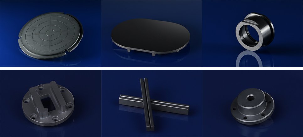
Typical Applications
Semiconductor Equipment:
SiC wafer carriers, susceptors, and etching chamber components due to high thermal conductivity and plasma resistance.Aerospace:
Lightweight structural parts and high-temperature bearings for engines and thermal protection systems.Optical Systems:
Mirror substrates and telescope structures requiring dimensional stability and low thermal expansion.Vacuum and Laser Systems:
Structural mounts and housings with excellent stiffness and ultra-flat surfaces.